Showing posts with label Radio. Show all posts

Rangkaian FM/AM Stereo Receiver CXA1538

Posted by Anonymous


Preview FM / AM Stereo Receiver CXA1538 IC is an IC CXA1538 bipoloar receiver designed specifically for FM / AM stereo receiver section includes high performance FM / AM IF amplifier, FM / AM detector, stereo FM demodulator, VCO Terminal, stereo indicator. FM / AM Stereo Receiver CXA1538 mapu suppress noise well at 40dBu. FM / AM Stereo Receiver CXA1538 has a detector signal that will make the change from stereo to mono mode when the received signal is weak around 10 -15 DBU. radioFM / AM Stereo Receiver CXA1538 has a track stereo and mono mode selection manually, the pin 3. FM / AM Stereo Receiver CXA1538 also has a soft muting that will work automatically when a low signal in the range of 23dB.
Series FM / AM Stereo Receiver CXA1538.
Features FM / AM Stereo Receiver CXA1538
Rangkaian FM/AM Stereo Receiver CXA1538

* Low power consumption (FM = 11.0 mA, AM = 8.5 mA, VCC = 6.0 V)
* LED tuning indicator
* LED indicator Stereo
* Muting circuit on FM
* Few external components
More about → Rangkaian FM/AM Stereo Receiver CXA1538

Function Generator with IC 8038 and LF351

Posted by Anonymous

Function Generator with IC 8038 and LF351 image

Function Generator with IC 8038 and LF351
Read detail :
Function Generator with IC 8038 and LF351-Built around a single 8038 waveform generator IC, this circuit produces sine, square or triangle waves from 20Hz to 200kHz in four switched ranges. There are both high and low level outputs which may be adjusted with the level control. This project makes a useful addition to any hobbyists workbench as well.

All of the waveform generation is produced by IC1. This versatile IC even has a sweep input, but is not used in this circuit. The IC contains an internal squarewave oscillator, the frequency of which is controlled by timing capacitors C1 – C4 and the 10k potentiometer. The tolerance of the capacitors should be 10% or better for stability. The squarewave is differentiated to produce a triangular wave, which in turn is shaped to produce a sine wave. All this is done internally, with a minimum of external components. The purity of the sine wave is adjusted by the two 100k preset resistors.

Function Generator with IC 8038 and LF351 - [Link]

source: http://www.electronics-lab.com/blog/?p=230
More about → Function Generator with IC 8038 and LF351

Sine wave generator Adjustable High/Low Frequency

Posted by Anonymous

Adjustable High Low Frequency Sine wave generator low distortion

Sine wave generator Adjustable High/Low Frequen-This circuit uses the versatile MAX038 function generator. Although in this circuit some of the advanced characteristics of this IC are disabled, you can generate Sine, Triangle, Square waves (adjusting A0 and A1 pins see datasheet on www.maxim-ic.com if you want other waves, use a switch).

The signal is amplified through a TCA0372 (from ONSEMI) Power opamp with current capability up to 1A and bandwitch up to 1 MHz.

I selected this particular frequency (122 Khz) because i needed a cheapo ESR-o-meter for my electrolytic capacitors to monitor their health as they have to discharge tens of amperes in less than 2 ms. At 122 KHz capacitive reactance is very low, and inductive reactance isn't so high, so forcing a current (es 200mA, using a precision resistor) through a capacitor and reading AC voltage drop accross it gives me an estimation of ESR (Vdrop/current). Of course inductive and capacitive reactance are still present, but negligible.

Let's back to the circuit.

Operation:
The 122 khz 2V p-p sine wave is generated by the MAX038 IC, its frequency can be calculated by the formula Freq (MHz) = Iin(uA) / C6 (pf) . Iin = 2,5V / R1 (25Kohm default). So the freq is 0,122 MHz . The resistor is for small adjustments, don't go under 10000 Kohm or above 40000 Kohm because the accuracy will drop. If you want multifrequency just use the multiposition switch with 820 pF, 8,2 nF , 82nF , 820 nf for 122Khz range 12,2Khz range 1220 Hz and 122 Hz. Fine tuning can be done adjusting R2 , the frequency can vary from 1,7x (Vfadj = -2,4) to 0,3x (Vfadj = 2,4) of the main frequency (when fadj is at 0V).

The sine wave output is feed into a TCA0372 1/2 opamp to achieve a gain from 1 to 5 (2V p-p, 10 V p-p), adjust the potenziometer and into a TCA0372 2/2 opamp buffer stage also present on the same IC.

Important:
Adjusting the frequency needs a frequency counter, so this circuit should be used on conjunction with a freq couter. The max current is 1A, but i would suggesto to not go above 0,5A to remain accurate. Needs a computer power supply with 12V,5V,-5V,-12V,GND to be operated, if you don't have one just use a multivoltage mains transformer (15 watt is enough) diode bridges (low current 1-2 Amps), smoothing capacitors 10000uF 16V, and voltage regulators such as LM7905 and LM7912.
Sine wave generator Adjustable High/Low Frequen

source: http://electronics-lab.com/projects/oscillators_timers/003/index.html
More about → Sine wave generator Adjustable High/Low Frequency

IR remote extender schematic

Posted by Anonymous

IR remote extender schematic image

This project describes how to build an IR remote control extender / repeater to control your electronic appliances from a remote location.

An IR detector module receives IR signal from remote control and two IR leds are re-emitting the signal to the appliance. You can place the IR emitting leds close to the device you would like to control using some wire and keep main unit close to remote control location. In the image at the left LEDs are soldered on the board. The circuit consists of three main parts, the IR receiver module, a 555 timer configured as an oscillator and the output / emitter stage. We will describe circuit operation below.

Circuit is designed by Andy Collinson and can be found here: http://www.zen22142.zen.co.uk

source: http://www.electronics-lab.com/
More about → IR remote extender schematic

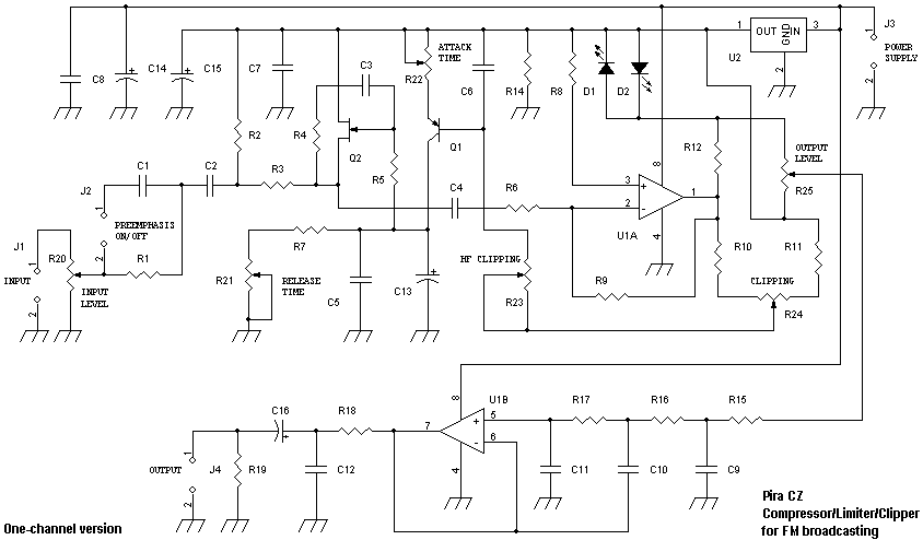
Skema Compressor/Limiter/Clipper for FM broadcasting

Posted by Anonymous

Skema Compressor/Limiter/Clipper for FM broadcastingScheme Compressor / Limiter / Clipper for FM broadcasting
More about → Skema Compressor/Limiter/Clipper for FM broadcasting

SKEMA PEMANCAR RADIO AM

Posted by Anonymous

SKEMA PEMANCAR RADIO AM
I'd love to raft the transmitter AM (MW and SW), but not yet. I've also seen scatter SW wrote using 3 tubes, fewer components were Dr. FM transmitter. In the SW transmitter that, I do not see ELCO, RESISTOR, and Trimmer. Which is in the transmitter box that is several transformers, ranging from small to large, there was also entwined PVC pipe with copper wire (such as home electrical wire installation). Also there are some components that I do not know the name and function.SKEMA PEMANCAR RADIO AM
More about → SKEMA PEMANCAR RADIO AM