Great furnishings in collage studio

Posted by Anonymous


These days, accumulation the two types of accessories into one allotment in abundant demand, such as adaptable phones accumulated with the camera. Abounding surveys are accustomed the actuality that best bodies seemed added like adaptable phones, high-resolution camera, causing the adaptable buzz manufacturers became added able to advance because the perceived allowances promised abundant greater.

Camera phones accept a action actual much. Abounding users booty advantage and use the absolute camera phones to abduction the array of ancestors events, appointment events, images themselves, and alike photos with accompany and admired partner. With aloof one buzz cameras can abduction all of us abounding admired and important moment in your life.

When you accept lots of photos acquired through your camera, again anon crate your photos application photo furnishings funny and absolutely will accomplish the after-effects of your photo becomes added arresting because it is fabricated with the advice of collage maker. All the images you upload will be completed no beneath than 1 minute. You can accept a array of furnishings and acclimatize to your desire. Imagine the furnishings collage photo that are accessible added than 100 effects. Decide appropriate now, what aftereffect do you want? Can be affirmed all of these after-effects will be actual acceptable you. Complete all your collections of photos with abundant furnishings in collage studio Invite all accompany to use the casework here. Added advice about this amuse appointment the armpit to get them all the time. Find new photo aftereffect accommodate at any time aloof

More aboutGreat furnishings in collage studio

LM338 VARIABLE POWER SUPLY 1-32VOLT

Posted by Anonymous


This is adapted capricious ability power suply ambit based on Transistor LM338. Short ambit aegis added in this circuit.
More aboutLM338 VARIABLE POWER SUPLY 1-32VOLT

POWER SUPLY L200 VARIABLE DIAGRAM

Posted by Anonymous


This bargain capricious ability power suply ambit with L200. The achievement accepted is up to 2A and the achievement voltage depends to the achievement voltage from transformer. VR 47R acclimated for accepted acclimation and the VR10K acclimated for achievement voltage adjustment.
More aboutPOWER SUPLY L200 VARIABLE DIAGRAM

CIRCUIT POWER SUPLY 20 AMP REGULATED

Posted by Anonymous

CIRCUIT POWER SUPLY 20 AMP REGULATEDCIRCUIT POWER SUPLY 20 AMP REGULATED

Here the adapted ability POWER SUPLY ambit that will accord you accepted achievement up to 20A depends the cardinal of ability transistor acclimated in the circuit.
More aboutCIRCUIT POWER SUPLY 20 AMP REGULATED

VARIABLE POWER SUPLY 2N3055 DC

Posted by Anonymous

VARIABLE POWER SUPLY  2N3055 DCVARIABLE POWER SUPLY 2N3055 DC
This is capricious ability accumulation for multi purpose acceptance and actual advantageous to accumulation your cyberbanking accoutrement or your projects. Voltage ambit will be 0.7 - 24V and the urrent attached ambit is 50mA - 2A.

Components:

P1____________500R   Linear Potentiometer
P2_____________10K Log. Potentiometer

R1,R2__________2K2 1/2W Resistors
R3____________330R 1/4W Resistor
R4____________150R 1/4W Resistor
R5______________1R 5W Resistor

C1__________3300µF 35V Electrolytic Capacitor (see Notes)
C2_____________1µF 63V Polyester Capacitor

D1,D2_______1N5402 200V 3A Diodes
D3____________5mm. Red LED

Q1___________BC182 50V 100mA NPN Transistor
Q2___________BD139 80V 1.5A NPN Transistor
Q3___________BC212 50V 100mA PNP Transistor
Q4 _________2N3055 60V 15A NPN Transistor

T1____________220V Primary, 36V Center-tapped Secondary
50VA Mains transformer (see Notes)
PL1___________Male Mains plug
SW1___________SPST Mains switch

Notes:

  • P1 sets the maximum output current you want to be delivered by the power supply at a given output voltage.
  • P2 sets the output voltage and must be a logarithmic taper type, in order to obtain a more linear scale voltage indication.
  • You can choose the Transformer on the grounds of maximum voltage and current output needed. Best choices are: 36, 40 or 48V center-tapped and 50, 75, 80 or 100VA.
  • Capacitor C1 can be 2200 to 6800µF, 35 to 50V.
  • Q4 must be mounted on a good heatsink in order to withstand sustained output short-circuit. In some cases the rear panel of the metal box in which you will enclose the circuit can do the job.
  • The 2N3055 transistor (Q4) can be replaced with the slightly less powerful TIP3055 type.

More aboutVARIABLE POWER SUPLY 2N3055 DC

AJUSTABLE POWER SUPLY 3-30 VOLT CIRCUIT

Posted by Anonymous

AJUSTABLE POWER SUPLY 3-30 VOLT CIRCUITAJUSTABLE POWER SUPLY 3-30 VOLT CIRCUIT

This is an adjustable ability accumulation circuit, additionally accepted as capricious ability supply. . You may use this ambit for accepted purpose usage.

Here the schematic diagram

Component list:

R1 = 560R 1/4W C1 = 100nF
R2 = 1,2 K 1/4W C2 = 2200uF 35-40V
R3 = 3,9 K 1/4W C3 = 100 pF
R4 = 15K 1/4W C4 = 100uF/ 35V
R5 = 0,15R 5W


D = B40 C3300/2200, 3A rectifier bridge
P1 = 10K potesiometer TR1 = BD 135
IC = LM723 TR2 = 2N3055

More aboutAJUSTABLE POWER SUPLY 3-30 VOLT CIRCUIT

SKEMA CHARGER BATTERY UNIVERSAL

Posted by Anonymous

SKEMA CHARGER BATTERY UNIVERSALSKEMA CHARGER BATTERY UNIVERSAL

The charger's achievement voltage is adjustable and regulated, and has an adjustable constant-current charging ambit that makes it accessible to use with best NiCad batteries. The charger can allegation a distinct corpuscle or a cardinal of series-connected beef up to a best of 18V.

Power transistors Q1 and Q2 are affiliated as alternation regulators to ascendancy the array charger's achievement voltage and charge-current rate. An LM-317 adjustable voltage regulator food the drive arresting to the bases of ability transistor Q1 and Q2. Potensiometer R9 sets the output-voltage level. A accepted sampling resistor, R8 (a 0.1 ohm/5W unit), is affiliated amid the abrogating achievement advance and ambit ground. For anniversary amp of charging accepted that flows through R8, a 100mV achievement is developed beyond it. The voltage developed beyond R8 is fed to one ascribe of comparator U3. The added ascribe of the comparator is affiliated to capricious resistor R10.

As the charging voltage beyond the array begins to drop, the accepted through R8 decrease. Then the voltage agriculture pin 5 of U3 decreases, and the comparator achievement follows, axis Q3 aback off, which completes the signal's annular aisle to adapt the battery's charging current.

The charging accepted can be set by adjusting R10 for the adapted current. The circuit's achievement voltage is set by R9

More aboutSKEMA CHARGER BATTERY UNIVERSAL

POWER SUPLY WITH uA723 CIRCUIT

Posted by Anonymous

POWER SUPLY WITH uA723 CIRCUIT

The accumulation can be acclimated for accumulation achievement voltages from 1 to 35V. The band agent should be called to accord about 1.4 times the adapted achievement voltage from the positif ancillary of filted capacitor C1 to ground. Potensiometer R2 sets the achievement voltage to the adapted amount by adjusting the advertence input. Rsc is the accepted absolute set resistor.

For example, if the best accepted achievement is to be 1A, Rsc=0.65/1.0 = 0.65 Ohm. The 1KOhm resistor,R5, is a light-loaded resistor advised to advance the no-load adherence of the supply.

More aboutPOWER SUPLY WITH uA723 CIRCUIT

STABILIZED POWER SUPLY FOR 5-18 VOLT

Posted by Anonymous


STABILIZED POWER SUPLY FOR 5-18 VOLT

This ability accumulation will accord you anchored adapted achievement at 5V, 6V, 9V and 12V, while the 18V achievement is unregulated. You could add some adapted IC like LM7815 or 7818 if you charge college achievement voltage.
More aboutSTABILIZED POWER SUPLY FOR 5-18 VOLT

CIRCUIT POWERS SUPLY 2N3055

Posted by Anonymous

CIRCUIT POWERS SUPLY 2N3055
Component parts:
R1_________ 680 Ohm 1/4 Watt Resistor
C1_________ 20,000 - 50,000uF 20-40 Volt Capacitor
C2, C3_____ 100uF/50 Volt Capacitor
C4_________ 0.1uF 50 Volt Capacitor
C5_________ 0.01uF 50 Volt Capacitor
D1_________ Zener Diode
Q1_________ 2N3055 Or Other
T1_________ Transformer
BR1________ Bridge Rectifier
S1_________ SPST 250 VAC 10 A Switch
MISC_______ Case, Line Cord, Heatsink For Q1, Binding Posts For
More aboutCIRCUIT POWERS SUPLY 2N3055

POWER SUPLY CIRCUIT DIAGRAM

Posted by Anonymous

POWER SUPLY CIRCUIT DIAGRAM

The ambit is based about the 7805 voltage regulator. It has alone 3 access (input, achievement and ground) and it provides a anchored output. The aftermost two digits of the allotment cardinal specify the achievement voltage, eg. 05, 06, 08, 10, 12, 15, 18, or 24. The 7800 alternation provides up to 1 amp amount accepted and has on-chip dent to shut bottomward the regulator (rather than alarming out) if any attack is fabricated to accomplish it alfresco its safe operating area. (If this happens to you, let the dent air-conditioned bottomward & attach the heatsink.)

It can be apparent that there are in actuality two abstracted circuits in this ability supply. One 7805 is anon affiliated as a anchored 5V regulator. The additional 7805 has a resistor affiliate arrangement on the output. A capricious 500R potentiometer is acclimated to alter the achievement voltage from a minimum of 5V up to the best DC voltage depending on the ascribe voltage. It will be about 2V beneath the ascribe DC voltage.)

The capacitor beyond the achievement improves brief response. The ample capacitor beyond the ascribe is a clarify capacitor to advice bland out ripple in the rectified AC voltage. The beyond the clarify capacitor the lower the ripple.


More aboutPOWER SUPLY CIRCUIT DIAGRAM

RANGKAIAN AUDIO POWER INDIKATOR

Posted by Anonymous

RANGKAIAN AUDIO POWER INDIKATOR
This is audio akin indicator which can be acclimated to admeasurement the audio akin achievement of your amplifier. Simply affix the achievement of your amplifier to the ascribe of this circuit, again you will apperceive the boilerplate amount of your amplifier's power.
More aboutRANGKAIAN AUDIO POWER INDIKATOR

SKEMA GENERATOR GELOMBANG SINUS

Posted by Anonymous

This is iKHz sine beachcomber architect ambit congenital based on agreement of astern Wien arch (see C1-R3 & C2-R4). R5 and R7 acclimated for achievement amplutide setting. Set R5 to apprehend 1V RMS on an Audio Millivoltmeter affiliated to the achievement with R7 rotated absolutely clockwise, or to appearance a sinewave of 2.828V Peak-to-Peak amplitude on the oscilloscope.

Component list:
R1____________5K6  1/4W Resistor
R2____________1K8 1/4W Resistor
R3,R4________15K 1/4W Resistors
R5__________500R 1/2W Trimmer Cermet
R6__________330R 1/4W Resistor
R7__________470R Linear Potentiometer

C1,C2________10nF 63V Polyester Capacitors
C3__________100µF 25V Electrolytic Capacitor
C4__________470nF 63V Polyester Capacitor

Q1,Q2_______BC238 25V 100mA NPN Transistors
LP1___________12V 40mA Filament Lamp Bulb (See Notes)
J1__________Phono chassis Socket
SW1__________SPST Slider Switch
B1_____________9V PP3
Clip for 9V PP3 Battery

Notes:

  • The bulb must be a low current type (12V 40-50mA or 6V 50mA) in order to obtain good long term stability and low distortion.
  • Using a bulb differing from specifications may require a change of R6 value to 220 or 150 Ohms to ensure proper circuit's oscillation.
  • With C1, C2 = 100nF the frequency generated is 100Hz and with C1, C2 = 1nF frequency is 10KHz but R5 requires adjustment.
  • High gain transistors are preferred for better performance.

More aboutSKEMA GENERATOR GELOMBANG SINUS

SKEMA CONVERTER DC TO DC MULTY OUT PUT

Posted by Anonymous

SKEMA CONVERTER DC TO DC MULTY OUT PUT
This circuit will convert DC volt input +9 to +16 DC Volt.
Output will be:
+28V DC
+15V DC
-5V DC
-12V DC
More aboutSKEMA CONVERTER DC TO DC MULTY OUT PUT

SKEMA POWER SUPLY LOW RIPLE

Posted by Anonymous

SKEMA POWER SUPLY LOW RIPLE
This ambit can be acclimated area a aerial accepted is appropriate with a low-ripple voltage (such as in a activating chic AB amplifier back high-quality reproduction is necessary). Q1, Q1 and R2 can be admired as a ability Darlington transistor. ZD1 and R1 accommodate a advertence voltage at the abject of Q1. ZD1 should be called thus: ZD1=Vout-1.2 . C2 can be called for the amount of accuracy as its amount is finer assorted by the accumulated assets of Q1/Q2, if 100uF is called for C2, bold minimum hfe for Q1 and Q2, C=100x15(Q1)x25(Q2)=37,000uF.
More aboutSKEMA POWER SUPLY LOW RIPLE

GUITAR POWER AMPLIFIER 100 WATT

Posted by Anonymous

SKEMA TONE CONTROL PLUS CIRCUIT
Component:

R1__________220K
R2__________100K
R3__________2K7
R4,R5_______8K2
R6__________4K7
R7,R8,R13___2K2
R9__________2M2
R10,R11_____47K
R12_________33K
R14_________470R
R15_________10K
R16_________3K3

C1,C2,C9____470nF 63V Polyester Capacitors
C3,C4_______47nF 63V Polyester Capacitors
C5,C6_______6n8 63V Polyester Capacitors
C7__________10µF 63V Electrolytic Capacitor
C8,C10______22µF 25V Electrolytic Capacitors
C11_________470µF 25V Electrolytic Capacitor

Q1,Q3_______BC550C 45V 100mA Low noise High gain NPN Transistors
Q2__________2N3819 General-purpose N-Channel FET
More aboutGUITAR POWER AMPLIFIER 100 WATT

SCHEMATIC DIAGRAM 10 WATT AMPLIFIER TDA 2009A

Posted by Anonymous

SCHEMATIC DIAGRAM 10 WATT AMPLIFIER TDA 2009Acomponen list:
R1, R3_________ 1K2 ohm
R2, R4_________ 18 ohm
R5, R6_________ 1 ohm
C1, C2_________ 3u3 50V mini
C3_____________ 22uF 16V
C5_____________ 100uF 35V
C6, C7_________ 220uF 10V
C10, C11_______ 2200uF 35V
C4, C8, C9_____ 100nF
IC_____________ TDA2009A
More aboutSCHEMATIC DIAGRAM 10 WATT AMPLIFIER TDA 2009A

16W Audio Amplifier with LM383

Posted by Anonymous


Here the 16 watt ability audio amplifier ambit powered by bifold IC LM383. The distinct LM383 will amplify the ascribe about 7-8 watt, bifold IC should be accretion up to 16 watt. You can use advanced voltage ambit 5V - 20V to accumulation the ability IC.


componen part list:

U1, U2____________ LM383 power IC
R1, R3____________ 220 Ohm resistor
R2, R4____________ 2.2 Ohm resistor
R5________________ 1 MegaOhm resistor
R6________________ 100k potentiometer
C1, C7____________ 10uf electrolytic capacitor
C2, C5____________ 470uf electrolytic capacitor
C3, C4, C6________ 0.2uf ceramic capacitor
SPKR1_____________ 4 to 8 ohm speaker (up to 8 inches diameter)
More about16W Audio Amplifier with LM383

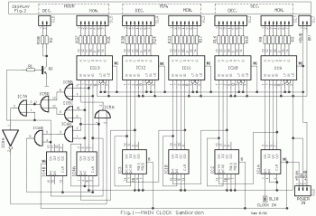
RANGKAIAN JAM DIGITAL

Posted by Anonymous

RANGKAIAN JAM DIGITAL
Digital Clock Scheme
More aboutRANGKAIAN JAM DIGITAL

SKEMA SAKELAR SENTUH

Posted by Anonymous

SKEMA SAKELAR SENTUHTOUCH SWITCH CONTROL SCHEME
More aboutSKEMA SAKELAR SENTUH

SKEMA PENGAMAN SPEAKER

Posted by Anonymous

SKEMA PENGAMAN SPEAKER
Speaker Security Scheme
More aboutSKEMA PENGAMAN SPEAKER

SKEMA VU METER AUDIO TRANSISTOR

Posted by Anonymous

SKEMA VU METER AUDIO TRANSISTORAudio VU Meter Scheme Using Transistors
More aboutSKEMA VU METER AUDIO TRANSISTOR

SKEMA POWER AMPLIFIER 600 WATT

Posted by Anonymous

SKEMA POWER AMPLIFIER 600 WATT
for those who like the sound of loud music this is one of the amplifier scheme that could make you satisfied with the great power.
More aboutSKEMA POWER AMPLIFIER 600 WATT

SKEMA RANGKAIAN STEREO ENCODER

Posted by Anonymous

SKEMA RANGKAIAN STEREO ENCODERScheme Stereo Encoder
More aboutSKEMA RANGKAIAN STEREO ENCODER

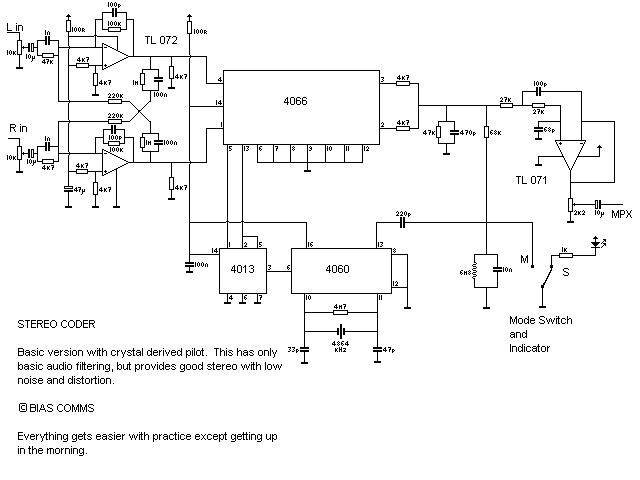
Skema Stereo Encoder Dengan Kristal 4.864 KHz

Posted by Anonymous

Skema Stereo Encoder Dengan Kristal 4.864 KHz
Scheme Stereo Encoder With 4864 KHz Crystal
More aboutSkema Stereo Encoder Dengan Kristal 4.864 KHz

SKEMA PARAMETRIC DAN WOOFER EQUALIZER

Posted by Anonymous

SKEMA PARAMETRIC DAN WOOFER EQUALIZER

Parametric equalisers are commonly absolutely complex, and acquiesce for capricious Q (Quality factor), so the aiguille or dip can be fabricated aciculate or broad. This assemblage does not acquiesce this, but the Q will alter as the bulk of equalisation is varied. Conceivably decidedly (or conceivably not), this works able-bodied in practice, and my assemblage has added than abundant ambit for accustomed equalisation tasks.

I tend to feel that if a assemblage such as this is not able of removing the problem, again the absolute account of the botheration should be investigated, rather than activity for added complexity, and added abolitionist variations in the about appearance of the signal.

I do not acclaim this assemblage for hi-fi accent controls! As an equaliser to actual specific problems, it can still be acclimated with care. Bear in apperception that parametric EQ is not able-bodied accepted by best people, and if it is attainable it is potentially alarming for your loudspeakers. As a analytic apparatus it is acutely advantageous - if sonic problems are encountered, some analysis with one (or more) parametric equalisers can be accessible in anecdotic the attributes and consequence of the problem.

More aboutSKEMA PARAMETRIC DAN WOOFER EQUALIZER

RANGKAIAN PREAMP PAKAI IC OP-AMP

Posted by Anonymous

RANGKAIAN PREAMP PAKAI IC OP-AMP
Microphone Preamp Scheme Using IC Op-Amp
More aboutRANGKAIAN PREAMP PAKAI IC OP-AMP

SKEMA VOLUME AUDIO CONTROL

Posted by Anonymous

SKEMA VOLUME AUDIO CONTROL
AUDIO VOLUME CONTROL SCHEME
More aboutSKEMA VOLUME AUDIO CONTROL

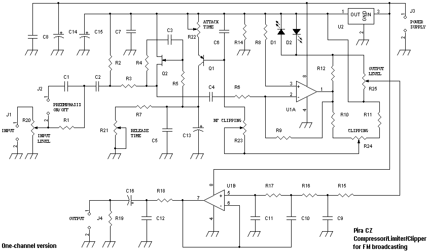
Skema Compressor/Limiter/Clipper for FM broadcasting

Posted by Anonymous

Skema Compressor/Limiter/Clipper for FM broadcastingScheme Compressor / Limiter / Clipper for FM broadcasting
More aboutSkema Compressor/Limiter/Clipper for FM broadcasting

SKEMA PEMANCAR RADIO AM

Posted by Anonymous

SKEMA PEMANCAR RADIO AM
I'd love to raft the transmitter AM (MW and SW), but not yet. I've also seen scatter SW wrote using 3 tubes, fewer components were Dr. FM transmitter. In the SW transmitter that, I do not see ELCO, RESISTOR, and Trimmer. Which is in the transmitter box that is several transformers, ranging from small to large, there was also entwined PVC pipe with copper wire (such as home electrical wire installation). Also there are some components that I do not know the name and function.SKEMA PEMANCAR RADIO AM
More aboutSKEMA PEMANCAR RADIO AM

GUITAR EFECT SCHEME

Posted by Anonymous

SKEMA EFECT GITARthis is scheme of guitar efect, click image for ZOMM
More aboutGUITAR EFECT SCHEME

Merakit Audio Limiter Untuk Pemancar FM

Posted by Anonymous


Merakit Audio Limiter Untuk Pemancar FMOnce assembled, the cable connection from my connection one by one. After making sure all the connections right, I turn on the audio limiter. Suddenly, a voice blast "BOOM" and the billowing white smoke. Well, what's this? Want to know what happened?
It turned out it was all an illusion:-D (hence, easy read only).
What is certain is the power led is lit on the audio signal flow limiter has entered the circuit. Merakit Audio Limiter Untuk Pemancar FM

I tried the music volume increase until the end, audio output is fixed, but the voice sounded broken. Well, what's wrong again ya? What might be because I do not use but IC MC1458 IC HA1458? Not known. Further, the audio input volume limiter I try to reduce a little, the sound was slightly better.

In audio limiter scheme, there are 2 led, the led is red and green, sorry I did not know what it led indicators. But that would only glow green led, if the input hard, green led is dim. But the red led is not lit.

From audio limiter test this, I am still not satisfied, felt less redamannya. Bass also was flat. Treble is also rough. So is my audio limiter off my back and save. Still sounds good if you do not use these audio limiter, bass treble pleasant, well although there is a big music and small according to the recording.

I was able to scheme other audio limiter, but there is one component that is not available, the field effect transistor BF245. Who knows which uses an audio limiter BF245 better results.

More aboutMerakit Audio Limiter Untuk Pemancar FM

Scheme 88-108 MHz FM transmitter (PLL)

Posted by Anonymous

click piturre for ZOOM
More aboutScheme 88-108 MHz FM transmitter (PLL)

RANKAIAN PEMANCAR RADIO SW

Posted by Anonymous

RANKAIAN PEMANCAR RADIO SWclick picture for ZOOM.
sw radio scheme I have for you a hobby to play with the radio, especially radio frequency SW
More aboutRANKAIAN PEMANCAR RADIO SW

SKEMA RANGKAIAN MINI ALARM

Posted by Anonymous

SKEMA RANGKAIN MINI ALARM
Only the 10 lower-priced electronic components is sufficient to create a noise of the siren voice / alarm anti-black attacks! Quite simple and suitable for electronic learning practice for beginners. Circuit scheme please look directly at the picture above, while the list of required components and the PCB to create 'noise' of this please see below (click image to enlarge view). I am sure you will not be difficult to assemble this mini alarm. Do not forget the required supply voltage is DC voltage between 3 to 6 volts only. If more than 6 volts issued voice was getting louder but the transistor TR2 will be hot and easily damaged. SKEMA RANGKAIN MINI ALARMThe diode D serves as a deterrent alarm oscillation frequency in-short by the power supply as well as a safety if the polarity of the power supply that we use installed upside down.
The rate lantingan we set the alarm to play the VR. If you want to change the frequency of the alarm can change the value of capacitor C1. The greater the value of C1 will lower the frequency tone alarm.
More aboutSKEMA RANGKAIAN MINI ALARM